
DevonianScotsman
Registered user
Hi all,
Just had to test the port into which the Indicator Relay plugs.
The problem that I've been having is that when the RHS Indicator Switch is pushed, nothing happens - so I needed to test whether it is the switch or Relay that was at fault.
Here's a brief set of instructions on how to test your Indicator Switches and the ground for the system that controls it.
---DISCLAIMER---
I accept no responsibility for any damage suffered by the rider, GSer or the bike concerned in performing these tests.
So, if you're still with me... We'll get started!
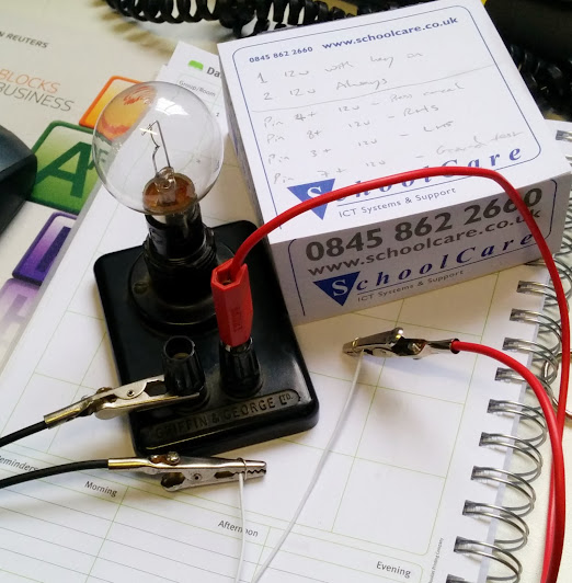
Firstly, you'll need to set up a test rig. I use a 12v bulb and some stiff wire - but a buzzer would work just fine.
My rig looks like this:
Next, you'll need to disconnect the relay. It looks like this:
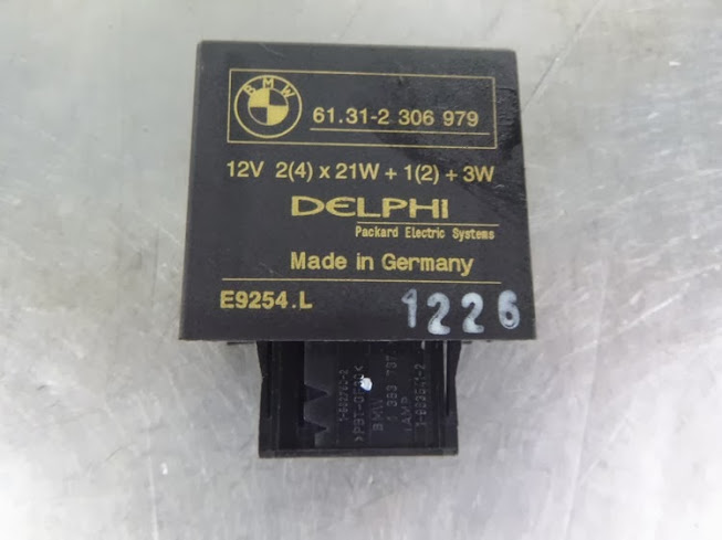
There's a little latch on top of the cable, which rotates through 90 degrees as the cable is removed. Be careful not to break this.
Once removed, you'll notice that the cable has a socket on the end of it with 12 ports. These are numbered on the socket, and laid out like this:

We'll need these numbers for testing - so work out which pins are which before carrying on.
Still with me? Good - let's get moving.
Firstly we are going to test ports 1 and 2 on the socket.
1 should carry 12 volts when the ignition is on, 2 should carry 12 volts always.
To test these, connect the negative terminal on your test rig to a good earth (the bike frame, port 7 on the relay socket or the negative terminal on the battery). Although it's best not to use port 7 on the socket, as we haven't tested it yet!
With the ignition off, connect the cable from the positive terminal of your test rig to port 2 on the socket. If it lights up, we're in business.
Turn the ignition on and connect the positive terminal on the rig to port 1 - once again, light is good, no light indicates a problem.
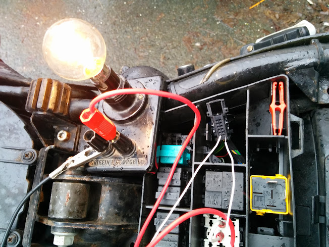
A successful test of port 1 looks like this:
Assuming that ports 1 and 2 are working, we need to test the LHS and RHS Indicator buttons, as well as the Cancel Button.
For this, we'll need to connect the positive terminal of the test rig to port 2 on the socket, providing 12 volts to the rig.
To test the Cancel Button:
Connect the negative terminal of the test rig to port 4 and press the Cancel Button. The light should illuminate.
To test the RHS Indicator Switch:
Connect the negative terminal of the test rig to port 8 and press the RHS Indicator Switch. The light should illuminate.
To test the LHS Indicator Switch:
Connect the negative terminal of the test rig to port 3 and press the LHS Indicator Switch. The light should illuminate.
Finally, we'll test the ground.
Connect the positive terminal of the rig to port 2 and the negative to port 7. The light should illuminate if all is fine.
I hope this helps someone - and questions, please give me a shout.
Rob
Just had to test the port into which the Indicator Relay plugs.
The problem that I've been having is that when the RHS Indicator Switch is pushed, nothing happens - so I needed to test whether it is the switch or Relay that was at fault.
Here's a brief set of instructions on how to test your Indicator Switches and the ground for the system that controls it.
---DISCLAIMER---
I accept no responsibility for any damage suffered by the rider, GSer or the bike concerned in performing these tests.
So, if you're still with me... We'll get started!
Firstly, you'll need to set up a test rig. I use a 12v bulb and some stiff wire - but a buzzer would work just fine.
My rig looks like this:
Next, you'll need to disconnect the relay. It looks like this:
There's a little latch on top of the cable, which rotates through 90 degrees as the cable is removed. Be careful not to break this.
Once removed, you'll notice that the cable has a socket on the end of it with 12 ports. These are numbered on the socket, and laid out like this:
We'll need these numbers for testing - so work out which pins are which before carrying on.
Still with me? Good - let's get moving.
Firstly we are going to test ports 1 and 2 on the socket.
1 should carry 12 volts when the ignition is on, 2 should carry 12 volts always.
To test these, connect the negative terminal on your test rig to a good earth (the bike frame, port 7 on the relay socket or the negative terminal on the battery). Although it's best not to use port 7 on the socket, as we haven't tested it yet!
With the ignition off, connect the cable from the positive terminal of your test rig to port 2 on the socket. If it lights up, we're in business.
Turn the ignition on and connect the positive terminal on the rig to port 1 - once again, light is good, no light indicates a problem.
A successful test of port 1 looks like this:
Assuming that ports 1 and 2 are working, we need to test the LHS and RHS Indicator buttons, as well as the Cancel Button.
For this, we'll need to connect the positive terminal of the test rig to port 2 on the socket, providing 12 volts to the rig.
To test the Cancel Button:
Connect the negative terminal of the test rig to port 4 and press the Cancel Button. The light should illuminate.
To test the RHS Indicator Switch:
Connect the negative terminal of the test rig to port 8 and press the RHS Indicator Switch. The light should illuminate.
To test the LHS Indicator Switch:
Connect the negative terminal of the test rig to port 3 and press the LHS Indicator Switch. The light should illuminate.
Finally, we'll test the ground.
Connect the positive terminal of the rig to port 2 and the negative to port 7. The light should illuminate if all is fine.
I hope this helps someone - and questions, please give me a shout.
Rob


